Inserting Parametric PLC Modules
AutoCAD Electrical can generate PLC I/O modules in different graphical styles through parametric generation technique on demand. These modules are generate by a database file and a library of symbol blocks. PLC I/O modules can be inserted as independent symbols. PLC modules behave like other schematic components. These modules are AutoCAD blocks containing attributes for connection points, tagging and so on.
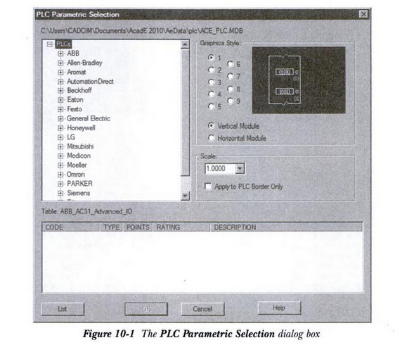
The Insert PLC (Parametric) tool is used to insert a PLC module parametrically. To do so, choose the Insert PLC (PLarametric) button from the Insert Components panel of the Schematic tab; the PLC Parametric Selection dialog box will be displayed, as shown in Figure 10-1. Using this dialog box, you can select the PLC module and its graphics that you want to insert in a drawing. The different options and areas in this dialog box are discussed next.
Manufacture Catalog Tree
The Manufacture Catalog tree, shown in Figure 10-2, displays a list of PLC modules. This list can be filtered by selecting the manufacturer, series, and type of PLC. The data displayed in the Manufacturer Catalog tree is stored in the ace_plc.mdb database file.

You can selet a PLC module from the Manufacturer Catalog tree. To do so, click on the + sign on the requried manfacturers module; PLC modules of the selected manafacturer will be displayed. Select the requried module from the module list; the detailed information of the selected module will be displayed at the lower part of the PLC Parametric Selection dialog box, as shown in Figure 10-3.
After specifying the required values in the I/O Point dialog box, choose the OK button from this dialog box; the I/O Address dialog box will be displayed, as shown in Figure 10-6. Using this dialog box, you can specify the address for the first I/O point.
The values in the Quick picks drop-down list are based on the values that you have specified in the I/O Point dialog box in the Rack and SLOT edit boxes. Select the required value from the Quick picks drop-down list; the value will be displayed in the Beginning address edit box. Alternatively, enter a required value for the first I/0 address of a PLC module in the Beginning address edit box. Note that the other I/O points of a module will be incremented based on the value specified in the Beginning address edit box.

After specifying the required options in the I/O Address dialog box, choose the OK button in this dialog box; the selected PLC module will be inserted into the drawing.
没有评论:
发表评论